How to connect a Smart Meter that won’t find a signal…
If you decide to take the action described below to make your communication module work as it should have done in the first place, then I cannot be held responsible for any repercussions, legal or otherwise. The aim of this guide is solely to improve the function of the SMETS2 communication module, so that it actually works…
Now we have that clear, then read on…
This explanation is designed to help facilitate the correct working of a communications module as used by SMETS2 electricity meters.
The Problem
Not all of us live in straightforward “box like” houses, and often our electricity supplies date back to a time before putting an unsightly plastic meter box on the front wall of a house was a normal thing to do..
Our house was built well before Electricity was even thought of…
The Smart Meter installation in our area (North) looks a bit like this:
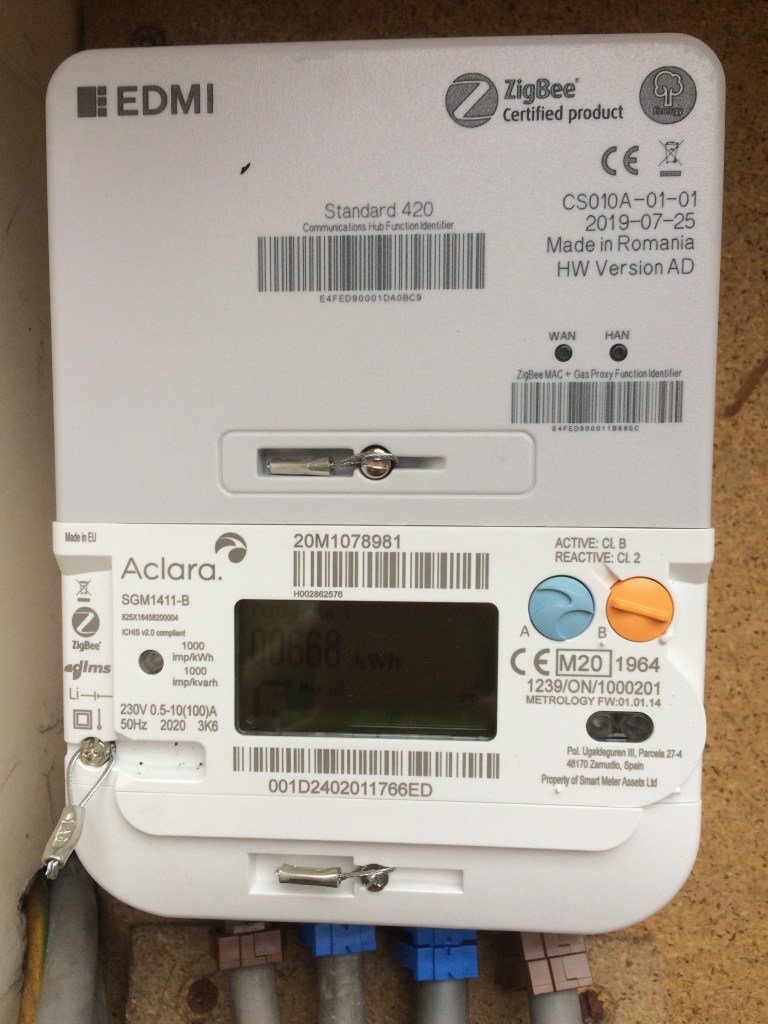
For some, the WAN Connection that’s needed to make your meter truly “Smart” and enable tariffs like Octopus Agile can have difficulty in establishing itself.
You’ll see this when the green WAN light on your Communication Hub flashes about once every 3 seconds or is solidly on. This means the hub is trying to find a WAN signal, but is failing.
A Faraday Cage
In our case, the meter is situated quite some distance away from the house deep inside a large well earthed, steel framed external building that is clad completely in insulated twin steel wall sheeting (also earthed).
It’s a perfect Faraday Cage. No radio signals can pass in or out of that building, so a SMETS2 smart meter with a communication hub was never going to work. Moving the meter is impossible for a whole variety of reasons – even if we wanted to.
Cellars and old buildings
Whilst other buildings may not have the laws of physics working so magnificently against them, the meter being in a cellar or behind thick stone walls can have a similar effect, attenuating the Communications Hub signal to such a degree that it just can’t connect.
This is often also because the signals being sent are not particularly strong, and in the North, they rely on Arqiva’s radio network. This is being improved – but it’s pretty patchy.
Fixing the problem…
Probably easier said than done, we decided to “move” the radio reception to somewhere there would be an excellent signal, and enable the Communications Hub to actually do what it was supposed to.
This meant pulling apart and investigating the EDMI Standard 420 Communications Hub and understanding what might be possible. I am a qualified electronics engineer with a decent background in analogue electronics including audio and radio. That said, the solution is simple, and well within the capabilities of anyone with some common sense and who can solder.
Breaking and Entering
Having removed the Communications Hub, the idea is to get into it without actually breaking anything…
Unfortunately, the moulding of this ABS case is really good and made to tight tolerances (congratulations EDMI, a nice bit of engineering). That also means the next step is the most difficult…
Removing the cover…
Much easier said than done.
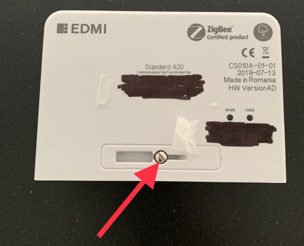
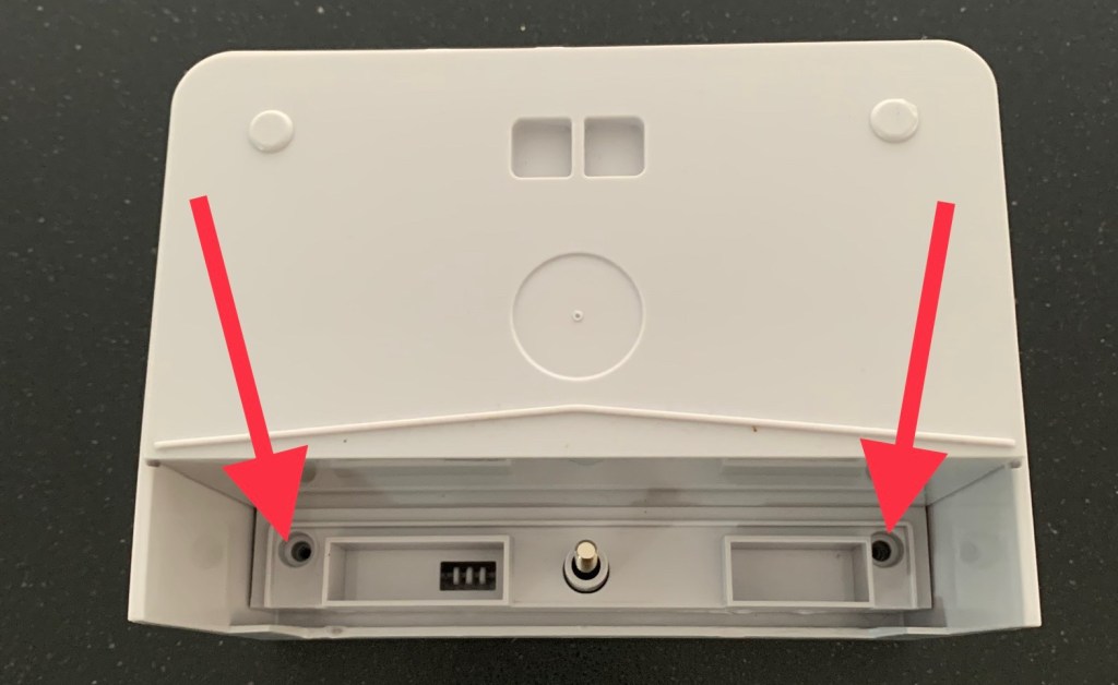
You now have the advantage of understanding that there are two moulded catches that must be released to separate the two halves of the clamshell case. In effect, you need to lift the top part of the cover by nearly 2 mm in two places simultaneously. This isn’t made easy, because the case also features a recessed edge to help prevent moisture ingress.


Possible techniques for opening Pandora’s box
I have a small but powerful lever suction cup that I acquired years ago. This placed on the top of the unit, and pulled upwards whilst separating the two halves (you need three hands!) . It worked for me after just four or five attempts. I didn’t know exactly where these lugs/catches were, so it took a few goes to hit the right place. At least you can see in the photos where these are.
Another technique I have successfully used in the past, is that of hot glue applied with a loop of solid wire attached. If attached in the right places, and a firm but steady pull on the wire is applied – it can have equally good results. Just go gently and vertically! The hot glue is relatively easy to remove later by warming gently with a heat gun and then rolling it off like Blu-Tack.
If you are prepared to be a bit more brutal, then some very deft leverage with suitable thin tools can also pop the catches, but do take care not to damage the boards underneath…
Going External

My thoughts were that if I were to put an antenna externally, and fed that signal straight back to the Communications Hub without much loss, then we might be in business.
Two antenna options…
As I thought about this, I wasn’t convinced that a small PCB planar antenna would have sufficient gain (“loudness”) to carry a UHF signal of 423 MHz down a long piece of coaxial aerial cable. In our case, we needed to get about 15 metres to the outside wall that faced our nearest Arqiva transmitter. These Arqiva locations are usually (but not always) co-located with the nearest TV transmitter.
Plan A – connect up the existing PCB antenna outside, and use good quality low loss coaxial cable and fittings to bring it back to the main board.
If that didn’t work, then
Plan B – connect up a home made tuned length “Slim Jim” antenna designed for 423 MHz. These are relatively simple to make and can theoretically boost signal gain by almost as much as three times – (actually 2.91x).
Ordering the parts
I worked out that for Plan A, I would need:
- 15 metres of good quality low loss, pre-terminated coaxial cable with SMA male connectors at each end.
- Two SMA pre-terminated female connector “pigtails” with about 10cm of small diameter coaxial cable and bare wire ends.
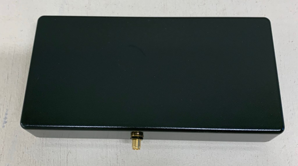
- A small plastic weatherproof box to go outside with the antenna inside it. (c. 130mm x 65mm x 20mm)
I got these from my usual electronics wholesalers, but Amazon, CPC and RS Components all have the stuff you may need. The total cost for me was about £17. You shouldn’t have to pay more than £25 for the same sort of stuff.
You should also have a solder removal tool (solder sucker) a good quality fine tipped soldering iron, some multicore solder and the ability to strip and prepare the coaxial cable/wire correctly
Time to get soldering…
Separating the boards.
Fortunately this is relatively easy due to the simplicity of construction. Ensuring that you are static free, take the two boards and de-solder both red wires at both ends. Be careful not to heat the PCB pads for too long as you do this – otherwise the track may lift, and you could end up ruining the boards.
When this is done, solder one of the female SMA connectors to the board as shown below, again being careful not to damage the board. The signal core of the coaxial cable should be attached to the central pad of the five shown, replacing one of the red wires. The outer shield however can go to any of the four outer pads in that group of five.
Try to keep he unshielded part of the signal wire as short as possible, and ensure that no stray ground/shield wires can touch any of the central pad or solder joint.
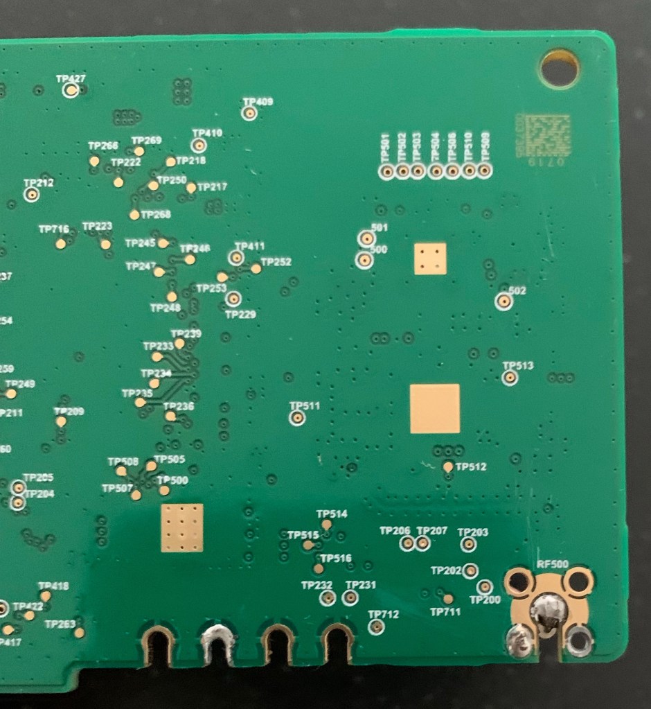
The completed main board..
The main board should now look like the picture below, with a 5 or 6cm “tail” attached with a female SMA connector.

The next trick is to find the right place to put the SMA connector in the other half of the plastic shell. To match my wiring needs and be discreet, I opted for the right hand side of the case. The old saying of “measure twice, cut once” is a good tip. Just be aware that there are areas of case overlap, so avoid these overlap areas when choosing a spot to drill the hole for the SMA antenna connector.

The Antenna

The other SMA pigtail should be attached as shown in the picture, with the signal wire going to the corner pad where one of the red wires was previously connected. The ground/shield wire is also connected exactly to where the other red wire was connected. For simplicity, I used a piece of the same red wire to “bridge” to the shield. Note that the unshielded part of the signal wire is again short. This helps preserve the low level signal.
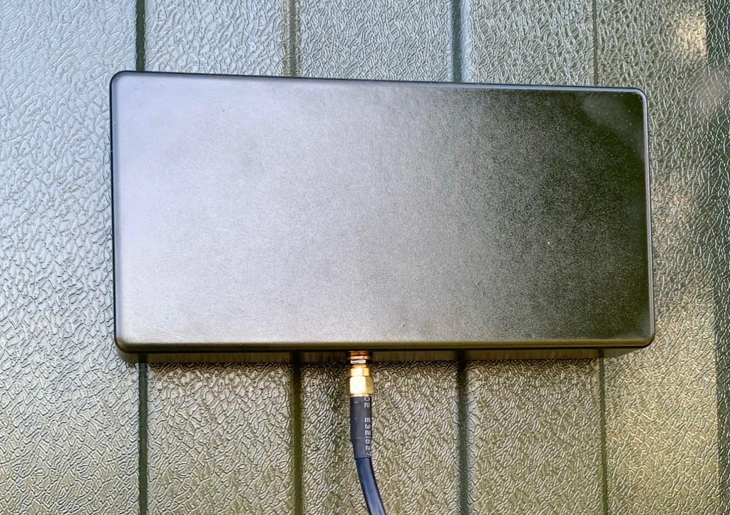
In our case the SMA connector is designed to exit the box at the bottom, and then once assembled, the box and connector are sealed with silicone mastic to ensure it stays waterproof. We also painted our antenna box the dark green colour of our building.
Plan A works…
For us, after a temporary fix to the building with gaffer tape – we clearly got a WAN signal within 24 hours of connecting the coaxial cable between the “new” external antenna and the Communications Hub.
We then permanently fixed the antenna into position and sealed the cable hole with a grommet and more mastic.
Conclusion
OK, so this solution is a bit fiddly, it’s probably going to be frowned upon by DCC = but all that has happened is that we’ve made something that was non- functioning finally work as it was intended.
I am sure that DCC don’t want folks poking about in the guts of the Communications Hub, but merely extending their antenna in a competent manner is about as basic as it gets…
It beats me why they don’t offer an external antenna version of the 420 Communications Hub because the board is clearly designed for an SMA PCB connector and it would probably solve a lot of issues.
Personally I would have preferred some form of secure wired VPN/IP Ethernet connector to the Meter, because then the data transmission would be fast and accurate with no antenna needed. That said, as an engineer, you have often to work with the crap you are given – and then find a way to make it better.
Hopefully this will see our SMETS2 metering working as it should for some considerable time.
I wish you the very best if you do this, but remember the disclaimer at the beginning…
Good luck!
Plan B
For those of you still struggling with signal after you have attempted this,…
Check the integrity of all the connections – making sure the signal isn’t accidentally going to ground through a stray strand of wire…
If you are still struggling, then with a bit more work – you could try building a Slim Jim antenna. I found this very helpful web page from another engineer in the Netherlands.
https://jeroen.steeman.org/Antenna/Slim-Jim-Antenna-Calculator
(Update – sadly this link no longer works – but Google Slim Jim antennas and you should be fine…)
You should use 423 MHz as the frequency, and the calculator and Jeroen’s excellent description describes how best to build an antenna that will fit into a 20mm ID plastic tube about 540mm long. Connect up the SMA connector and coaxial cable as he describes , and you should pull in a decent signal that’s far better than the small PCB antenna. A tip for maintaining the rigidity and the “gap” of the Slim Jim antenna is to either use a blob of hot glue between the ends of the wire – or heat shrink tubing…
In the past I have used both techniques – and both work.
